Monza holds a special place on the calendar, owing to the unique challenge that it poses to engineers and drivers alike. While higher top speeds are achieved elsewhere, its unique layout prompts many designers to create specific rear wing designs for this one race each year.
]]>Mercedes carried a fair amount of rear wing when compared with some rivals but, as we can see from this comparison it’s much less than we’ve seen it use at any point throughout the season so far, with the wing featuring a conventional shape and no Gurney flap on the upper flap's trailing edge. In Austria, it used a single pillar arrangement, a sizable top flap complete with a deep Gurney flap on the trailing edge.
For the Hungarian GP, it went for a full downforce rear wing and included a double element T-Wing to supplement it. The rear wing featured a twin mounting pillar configuration, which was favored in order to reduce the wing's tendency to be pulled around by the associated loads. A deeper mainplane and top flap also accompanied them, along with the retention of the deep Gurney flap. But, note how it also expanded the central V in the upper flap to try and offset some of the additional drag that would be created.
Another slightly revised layout appeared for the races at Silverstone, which was loosely based around the same design as the one seen in Austria. To reduce drag and improve their top speed on the ex-airfield’s long straights, Mercedes removed the Gurney flap from the trailing edge of the upper flap. It was a return to a high downforce configuration for the Spanish GP but, rather than the double element T-wing, it favored a single element version.
Then to Belgium and the challenges of Spa-Francorchamps, where all of the teams have to balance their desire to reduce drag over the need for downforce in sector two. Once again the team opted for a setup similar to the one seen at Silverstone but ditched the Gurney flap on the trailing edge of the upper flap as it looked to strip off some downforce whilst compromising balance a little.

Red Bull Racing RB16 rear view
Photo by: Motorsport Images
Red Bull continued to strip back downforce for the Italian GP in an effort to boost straight-line speed. Both rear wing designs featured a gentle spoon shaping to the mainplane, albeit with the Monza spec pegged at a shallower angle.

Red Bull Racing RB16 side view
Photo by: Motorsport Images
As you can see from both comparative images the chord on the wing used in Monza (right) is significantly shorter than the one used at Spa, with the flap effectively having the trailing edge lopped off all the way past the point where the central V groove previously existed. This also resulted in a change to the position of DRS adjuster, whilst you’ll also note the central mounting pillars are also different to reduce their aerodynamic impact.
Let's take a look at the other cars on the grid, and how they all compared.
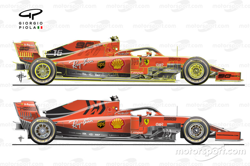
Ferrari SF1000 rearview Belgian GP vs Italian GP

Photo by: Giorgio Piola
Ferrari tested the Monza specification rear wing early-on during the Spa weekend. As shown in this comparison it is much lower downforce than the one that the team actually used by the team in Belgium. The T-Wing was also disposed of.
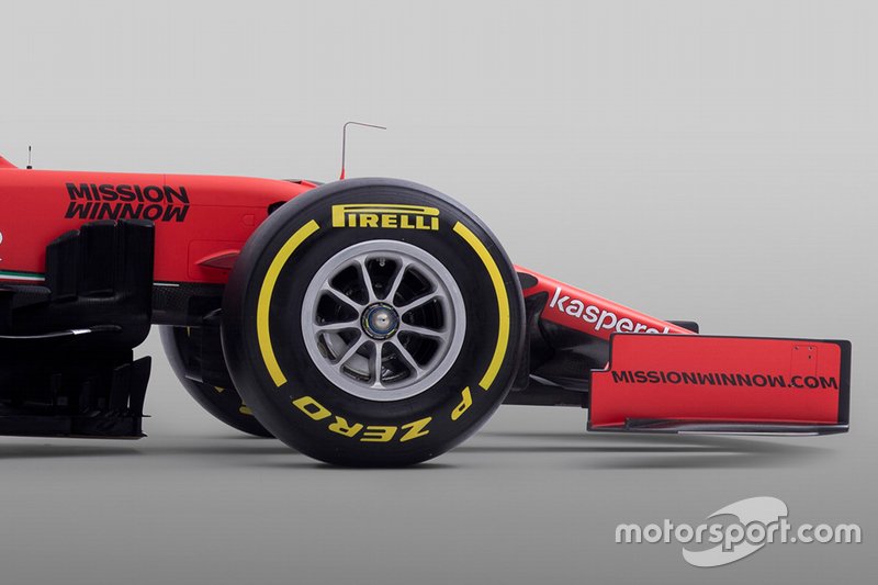
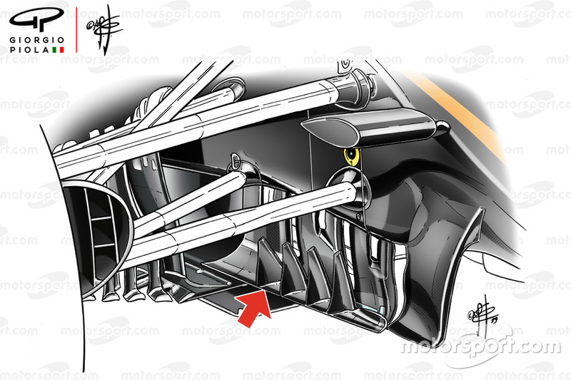
Ferrari SF1000 front wing detail

Photo by: Giorgio Piola
In order to take some load off the front end and balance out efforts at the rear of the car, the Scuderia also made changes to the front wing, cutting down the trailing edge of the innermost portion of the upper flap.
AlphaTauri AT01 front wing Italian GP

Photo by: Giorgio Piola
AlphaTauri didn’t have a one-off Monza special package, as it already used the extremely low downforce package at the Belgian GP. This included changes at the front and rear of the car, with the team sporting perhaps one of the most aggressive front wing solutions on the grid, as it sliced a significant portion off the front wing’s upper flap. It’s a decision that’s echoed up and down the field as teams know it provides a cost-effective solution and if necessary can be trimmed further on-site.
McLaren MCL35 rear

Photo by: Motorsport Images
McLaren, having already opted for a more conventional low-downforce offering at the Belgian GP, took things a stage further for the Italian GP by reducing the overall size of its wing to reduce downforce and drag.
Rear wing and DRS actuator on the car of Daniel Ricciardo, Renault F1 Team R.S.20

Photo by: Mark Sutton / Motorsport Images
Renault had already trimmed its car out to a downforce level akin to what you’d expect for Monza in Belgium last week. As such, it ran a very similar arrangement this week, meaning the straight line boost it appeared to have against some of their rivals last week was inevitably quashed.
Lance Stroll, Racing Point RP20

Photo by: Mark Sutton / Motorsport Images
Racing Point opted for a similar rear wing arrangement in Italy as used at Spa, putting more downforce at its disposal than competitors which is able to offset with the Mercedes power unit. This gives extra stability in the low-speed corners and increases the lifespan of the tires. It’s also worth noting that both drivers opted to use the T-Wing at the Italian GP, whereas in Belgium, where you’d expect them to use it, they did not.
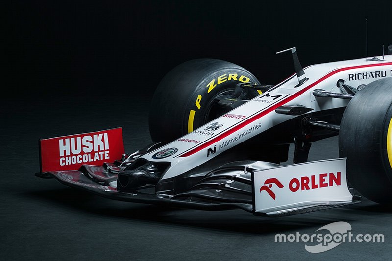
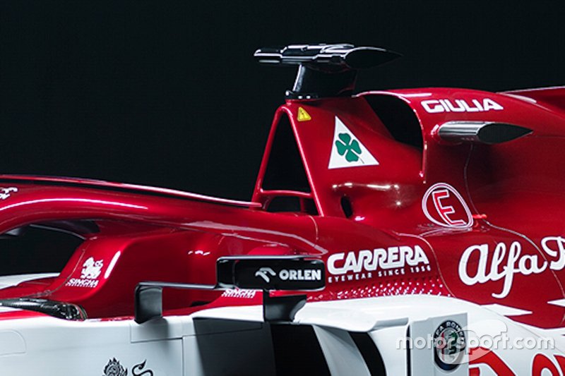
Antonio Giovinazzi, Alfa Romeo Racing C39

Photo by: Mark Sutton / Motorsport Images
Alfa Romeo briefly trialed its Monza specification rear wing at the Belgian GP. The wing itself is particularly low downforce for the team and saw Raikkonen rocket to the top of the speed traps at several points during the weekend, even though the team is struggling with a lack of straight-line speed owing to the Ferrari power unit. The unique feature of this rear wing is the mounting pillars, which have had the curved element at the top unceremoniously hacked off.
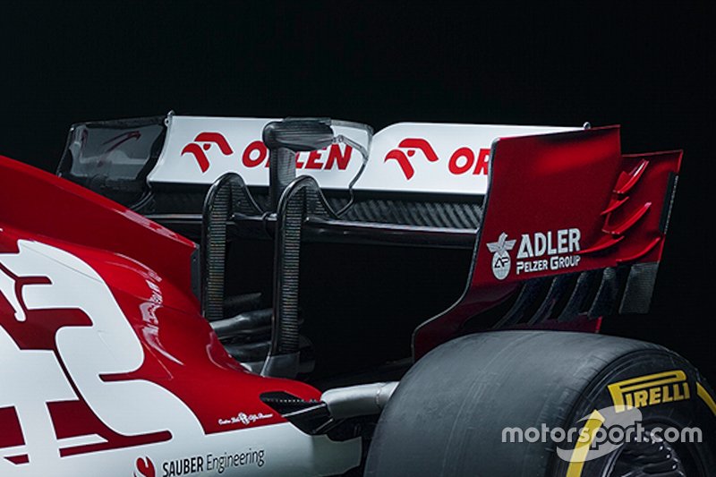
The rear wing of Kimi Raikkonen, Alfa Romeo Racing C39

Photo by: Mark Sutton / Motorsport Images
As a comparison here’s the rear wing raced by Alfa Romeo in Belgium, with a spoon-shaped mainplane used in order to try and retain downforce in the central portion of the wing, while reducing drag at the outer section.
Alfa Romeo Racing C39 rear wing pillar detail comparison

Photo by: Giorgio Piola
Here’s a comparison of the two styles of mounting pillars that have been used by Alfa Romeo up until now, with the ones used in Italy a variation on the taller ones on the left.
Kevin Magnussen, Haas VF-20

Photo by: Mark Sutton / Motorsport Images
Haas has, for a number of years, using a distinctive bow-tie shaped trailing edge on the upper flap of its rear wing design for the Belgian and Italian Grands Prix. This seems to work contrary to the rest of the grid in many respects, as while others are keen to lessen the tip vortex by reducing the height of the flap at the outer corner, it does this further inboard at the juncture with the slot gap separators.
Haas VF-18 rear wing, Belgian GP

Photo by: Giorgio Piola
It’s a design that the team has used for the last three years, with this illustration of the wing used on the 2018 challenger pointing out where the trailing edge of the upper flap descends toward the slot gap separator.
George Russell, Williams FW43

Photo by: Mark Sutton / Motorsport Images
Williams had an alarmingly large rear wing on the FW43 at the Italian GP. While the Mercedes power unit can help to offset some of the drag penalty that ensues, it’s clear that it opted not to spend time and resource on a one-off wing design that would have little to no benefit elsewhere on the calendar.
Roy Nissany, Williams FW43

Photo by: Charles Coates / Motorsport Images
Taking over from George Russell in FP1, Roy Nissany also ran the FW43 in even higher downforce trim, utilizing the spoon-shaped rear wing and double T-Wing combo.


 Giorgio Piola and Sutton Images bring you a selection of the best technical images from the Barcelona pitlane and track action on the first morning of Formula 1 testing in 2020.